
REVOPOINT / Scan-to-print & CAD / Applications
The easier-to-find replacement tank can have the right general shape and still miss the original mounting points. Scanning both versions gives you a way to see what an adapter would need to connect before you start drawing it.
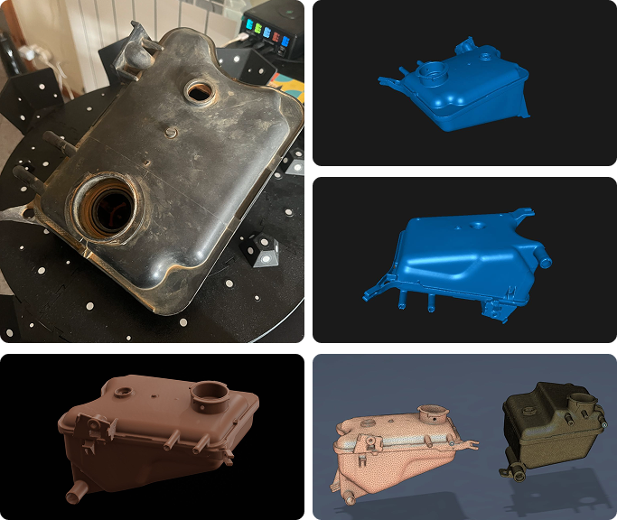
In a POP 4 community case shared by REVOPOINT, Tiago Cardoso collected scan references for two coolant reservoirs used with the XUD11 engine. The reservoirs suit the same engine application, but their mounts sit in different places. His aim was to plan an adapter for the more readily available tank while keeping the original mounting points.
What the cover shows: A physical reservoir, several scan views and the two digital references side by side. The shared material documents the comparison and design intent, not a completed installation or road test.
1. Compare the mounts, not just the outline
The two tank bodies do not have to match exactly for the comparison to be useful. Identify the fixing faces and fastener positions that determine how each tank sits. Comparing those features gives you more useful information than lining up the outer shells by eye.
For a similar project, mark which features must be captured clearly before you scan. Check the edges of mounting tabs and the geometry around the holes. If a fixing point is hidden or poorly captured, record a separate view or measure it directly; do not assume a smoothed mesh fills the gap accurately.
2. Turn the difference into an adapter brief
Think of the job as two interfaces. One side of the proposed adapter has to line up with the original mounting locations; the other has to support the replacement reservoir in the intended position. Comparing the scans helps you see the offset and orientation between those two sets of features.
Use the scan as a reference for an editable design. Independently check the key dimensions and inspect the available space around the tank, including hose routing and access to the cap. The newsletter does not identify the scanning mode or report measured tolerances, so the case is useful for planning the workflow, not for setting a precision target.
3. Check fit on the physical parts
Before committing to a finished part, compare your design against both physical interfaces. A fit-check mock-up can reveal a misplaced hole or an awkward clearance. It does not establish suitability for vehicle use; material, loads, temperature and vibration need their own assessment.
This is where two scans can save a round of guesswork: they let you compare what is available with what must stay in place. For the next CAD and prototyping steps, see our scan-to-CAD workflow guide.
Explore REVOPOINT POP 4 at Creality AU
If you are capturing geometry for a fit or design comparison, check the POP 4 packages and the computer requirements for the mode you intend to use. Paid CAD and inspection software are separate choices; check the selected bundle for inclusions.
View POP 4 and package options →Community project by Tiago Cardoso, shared by REVOPOINT. Original case image supplied by REVOPOINT and used with permission. Creality AU did not perform or validate this conversion.